Injection molding debinding units MDU-30 to MDU-3000

Modern injection molding debinding units enable high quality and cost efficient production cycles. 

For small batches of injection molding components the unit type MDU unites debinding, vacuum drying and solving recycling in one unit. Medium and big batches are handled by two simultaneously working and communicating units: one debinding and drying unit and one solvent recycling unit.

ONE FOR MANY

Each injection molding system has its own demands on the debinding medium to be used. But even for different systems, you will need only one debinding unit:

On request, the DesbaTec MDU Series can be equipped in a way, so that you are able to work with several different injection molding systems and solvents, but also with water.

For this purpose, the system will be equipped with several storage containers and programs for different debinding media.

After that you just choose which medium you want to use in the debinding process. The fully automatic PLC control does the rest.


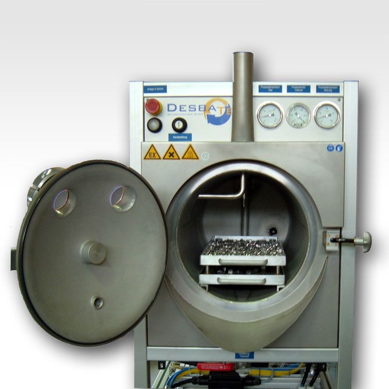
The debinding in units of the MDU series takes place under vacuum. After loading the debinding reactor with parts it is evacuated using a vacuum unit. As soon as the desired vacuum value is reached, the reactor chamber is flooded with solvent. The binder is removed from the green parts during the debinding process using tempered solvent in an injection-circulation procedure. This special procedure provides a high debinding rate even with parts of varying form and geometry.

For reduction of emission the solvent is cooled throughout the discharging process. At the end of the debinding process the solvent then is discharged into a integrated buffer tank.

During the following drying process the parts are dried with inerting gas injection washing under vacuum. The injection method here also provides optimal drying rates even with highly varying parts. The solvent vapors which result from the drying are condensed in a special heat-exchanger and are fed back into the process.

In the last process step the vacuum distillation of the solvent (or water) which is contaminated with the binder takes place, so that after that the solvent can be reused for a fresh debinding process.

Depending on the required throughput, the system consists of either a combined debinding and destillation unit or two separate, coordinated and communicating plants for debinding and distillation.


Debinding reactor/ distillation unit
 
Double-walled vessel
Continous, freely adjustable level measurement between 50% and 95%
-solvent circulation pump
Safety closure with O-ring seal
Basket for injection molded parts made of stainless steel or aluminum, size variable, mesh size up to <0,5mm
Vessel lamp in -design
Pneumatic drain ball valve for automatic discharge of liquid residues
Vessel interior electropolished/ solvent & temperature resistant anti-stick coating

 = Standard,   = Optional

Vacuum unit
 
Vacuum pump in  -design
Liquid ring vacuum pump, up to 35mbar, low maintenance
High-performance chemistry diagphragm pump, up to 10mbar
Dry running high performance pump, up to 1mbar, low maintenance

 = Standard,   = Optional

Heating
 
Heating in  -design
PID-controlled heat carrier heating
Temperature ramp function with 3 different temperature/ time presettings
Temperature ramp function with up to 7 different temperature/ time presettings

 = Standard,   = Optional

Frame variants
up to MDU-300 from MDU-400
Anodized, conductive aluminum profile frame
including panel sheets
Conductive, painted steel frame
Powder coated, conductive steel frame
Galvanized, conductive steel frame
Conductive stainless steel frame

 = Standard,   = Optional

Safety/ system integration
 
Explosion protection class EX II 3 G c IIA T3 (with inerting and suction)
Inerting unit
Suction hood at rigging aperture
Explosion protection class EX II 2 G c IIA T3 (without inerting/ suction)

 = Standard,   = Optional

Control system
 
Fully automatic, PLC operated system
Designed for monitoring free 24h operation
Delay timer for night/ weekend operation
Including 15m cable loom (from unit to switching cabinet)
At unit  
     On-/ off-switch
      -operation indicator lamp
     Emergency stop palm button
At switching cabinet  
     Graphics display and operating terminal at cabinet door, monochromatic, 16 gradations, touchscreen
     Operation indicator lamp
     Error indicator lamp
     Emergency stop palm button
     PID-controller & display
50m cable loom
At unit  
      -error indicator lamp
     Graphics and operating terminal in  -design
At switching cabinet  
     Graphics and operating terminal with color display, touchscreen

 = Standard,   = Optional

Optional accessories
 
Integratable container for fresh/ contaminated goods
External, single or double-walled container for fresh/ contaminated goods
Vapor recovery pipeline between fresh goods and contaminated goods tank for emission reduction
Safety collecting drip pan according to water ressources act (WHG)

 = Standard,   = Optional

 
Service
 
24 months warranty
Pan-european 24h on-site service
Express shipment of spare parts
Up to 60 months warranty
Remote maintenance through automation device or modem
Support at the creating of explosion protection document

 = Standard,   = Optional

Outstanding characteristics
 
Wetted parts in stainless steel, including double jacket for heat carrier
Stainless steel heat exchanger, welded

 = Standard,   = Optional


Further options on request


Redundant heating regulation
  • Temperature measurement in the reactor and in the heating carrier for constant debinding temperature
 
Realtime pressure measurement with EX-transducer
  • for continous monitoring of the debinding process
  • for automatic release of the solvent filling
  • for regulation of the reactor inerting


Continous level measurement through capacitive EX-probe
  • Freely adjustable levels for regulation of the automatic filling and discharge
  • Analysis and graphical display at the touchpanel display
  • Permanent leak test during the debinding process

Injection circulation
  • Special circulation procedure for high debinding rates even with parts of varying form and size


Inerting gas injection washing under vacuum
  • Optimal drying rate even with parts of varying form and size


Closed tank system with vapor recovery pipeline
  • Best emission/ environment protection
  • Minimal solvent loss
  • Increased explosion protection
 
Systems engineering according to european regulations
  • Highest operational safety
 

  • Reactor volume (l)
  • Overall capacity ca. (l)
  • Nominal distillation rate (l/h) (1)
  • Process pressure (bar)
  • Process temperature max. (°C) (2)
  • Max. volume for molded parts (m³)
  • Solvent circulation rate (l/h) (10)
  • Thermal oil heating
  • Protection class with inerting and suction
  • Power input normal operation ca. (kW)
  • Voltage (3)
  • Frequency (3)
  • Coolant requirements (m³) (7)
  • Width (mm)
  • Height (mm) (4)
  • Depth (mm)
  • Net weight ca. (kg)
  • Weight incl. solvent container (kg) ca. (12)
  • Related vacuum unit
  • Vacuum pressure max. (mbar) (5)
  • Max. suction capacity (m³/h) (6)
  • Weight ca. (kg)

MDU-30

  • 30
  • 26
  • 6-10
  • -1,0 to +0,5
  • 100°
  • 0,03
  • 5-30
  • integrated
  • EX II 3 G c IIA T3
  • 2,0
  • 230/ 400V, 3PH
  • 50Hz
  • 1,0
  • 590
  • 1600
  • 1000
  • 285
  • 390
  • DT-6
  • 35
  • 6
  • 30

MDU-60

  • 60
  • 54
  • 10-16
  • -1,0 to +0,5
  • 100°
  • 0,06
  • 5-30
  • integrated
  • EX II 3 G c IIA T3
  • 2,5
  • 230/ 400V, 3Ph
  • 50Hz
  • 1,3
  • 590
  • 1600
  • 1250
  • 320
  • 420
  • DT-10
  • 35
  • 10
  • 30

MDU-135

  • 135
  • 120
  • 18-30
  • -1,0 to +0,5
  • 100°
  • 0,09
  • 10-60
  • integrated
  • EX II 3 G c IIA T3
  • 3,5
  • 230/ 400V, 3Ph
  • 50Hz
  • 1,6
  • 850
  • 1600
  • 1350
  • 430
  • 680
  • DT-25
  • 35
  • 25
  • 65
  • Reactor volume (l)
  • Overall capacity ca. (l)
  • Nominal distillation rate (l/h) (1)
  • Process pressure (bar)
  • Process temperature max. (°C) (2)
  • Max. volume for molded parts (m³)
  • Solvent circulation rate (l/h) (10)
  • Thermal oil heating
  • Protection class with inerting and suction
  • Power input normal operation ca. (kW)
  • Voltage (3)
  • Frequency (3)
  • Coolant requirements (m³) (7)
  • Width (mm)
  • Height (mm) (4)
  • Depth (mm)
  • Net weight ca. (kg)
  • Weight incl. solvent container (kg) ca. (12)
  • Related vacuum unit
  • Vacuum pressure max. (mbar) (5)
  • Max. suction capacity (m³/h) (6)
  • Weight ca. (kg)

MDU-265

  • 265
  • 235
  • 30-60
  • -1,0 to +0,5
  • 100°
  • 0,19
  • 10-60
  • separate (8)
  • EX II 3 G c IIA T3
  • 5,5
  • 230/ 400V, 3PH
  • 50Hz
  • 2,0
  • 850
  • 1600
  • 2000
  • 540
  • 790
  • DT-25
  • 35
  • 25
  • 65

MDU-500

  • 500
  • 450
  • 70-140
  • -1,0 to +0,5
  • 100°
  • 0,30
  • 20-100
  • separate (8)
  • EX II 3 G c IIA T3
  • 11,0
  • 230/ 400V, 3Ph
  • 50Hz
  • 3,0
  • 1000
  • 1650
  • 1600
  • 600
  • -
  • DT-30
  • 35
  • 30
  • 65

MDU-650

  • 650
  • 590
  • 90-150
  • -1,0 to +0,5
  • 100°
  • 0,45
  • 20-100
  • separate (8)
  • EX II 3 G c IIA T3
  • 14,5
  • 230/ 400V, 3Ph
  • 50Hz
  • 3,6
  • 1000
  • 1650
  • 2500
  • 700
  • -
  • DT-30
  • 35
  • 30
  • 65

(1) depending on solvent, operating conditions, level of contamination and water content, (2) higher temperatures possible, (3) further on request, (4) depending on residue container, (5) vacuum system for up to 1mbar possible, (6) Operating liquid H2O at 15°C, at 50Hz, (7) at max 15°C, (8) integratable on request, (9) depending on quantity and size of injection molded parts, (10) adjustable, (11) Optional EX II 2 G c IIA T3 possible, (12) net weight incl. integrated solvent container. Solvent container seperate from unit size 320 and abo

The technical data stated above are to be regarded as orientation, as every unit is built and developed according to your whishes and requirements. Changes, errors and omissions excepted. Photos and images can differ from actual quotation.


TOP